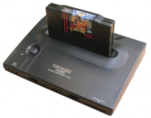
I am using a NEOGEO AES3-5 unit for the switchless mod today
Rom Part: piggyback
I added a second Bios from Razoola the UNIBIOS. You can get it at www.wolfsoft.de or unibios.free.fr
Here you can find a good tutorial for piggyback the UNIBIOS http://www.mmmonkey.co.uk/
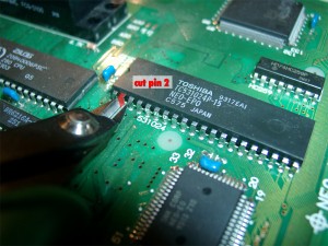
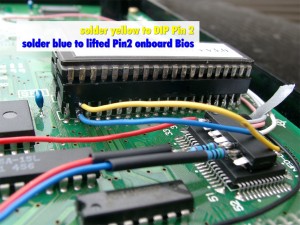
First you have cut pin 2 of the onboard Bio and lift the pin up:
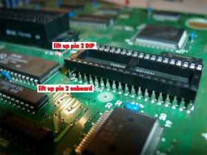
use a DIP 40 socket to make a future replacement easier
Lift up pin 2 of the mainboard and pin 2 of the DIP-socket
The PIC 16F630 Part
As usually I am using the switchless mod from seb http://seb.riot.org/saturnmod/
And the inspiration from Pete Grimes Site: http://www.mmmonkey.co.uk/
This time I can’t use sebs pic code „out of the box“.
I have done some lite modifications to the code.
50/60Hz switching is inverted at the NeoGeo and NeoGeo can’t switch between 50/60 Hz during operation. So it is needed to do a reset after switching 50/60Hz.
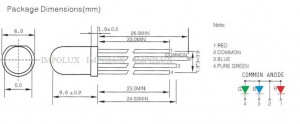
The Country Mode must reduced from 3 to 2 and I have done some slight changes for make a RGB-LED working. The difference at the RGB-LED it is wired common Anode
You will find the source code here.
PIC 16F630 Wiring
red wire PIC Pin 1 (5V) taken from IC HC04 Pin 14
black wire PIC Pin 14 (GND) taken from IC HC04 Pin 7
red wire PIC Pin 5 to RGB-LED (Resistor 150Ohm)
blue wire PIC Pin 6 to RGB-LED (Resistor 150Ohm)
yellow wire PIC Pin 8 to lifted Pin 2 of the DIP-socket
blue wire PIC Pin 10 to lifted Pin 2 of the onboard Bios
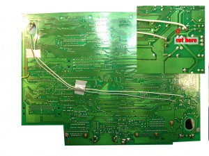
white wire PIC Pin 11 to solder site of mainboard (Reset Signal)
pink wire PIC Pin 12 to PAL Jumper right site (LSPC2-A2 TSOP Pin 64)
grey wire PIC Pin 13 to solder site of mainboard (Reset Button)
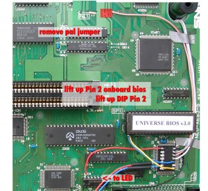
remove the pal jumper, solder pink to the right site of the jumper
(left site of PAL1 5V, right site to LSPC2-A2 TSOP Pin 64 for 50/60Hz definition)
Here you can see the lifted pins
on the solder site you have to cut one circuit (see red marked area) and solder grey and white
(to split the original Reset Button Signal and make use of the Reset Button via the PIC)
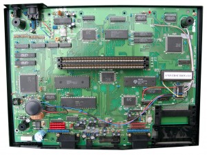
complete mainboard top site
The black wire at the RGB-Led under the Reset Buttons is carrying 5V and taken from a nearby IC
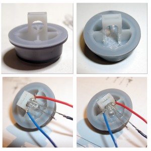
Now you have to add the RGB Led to the power switch, with help of a dremel.
I done it the same way as pete from www.mmmonkey.co.uk
For more power I am using now a RGB-Led with black wire common Anode 5V
english video
german Video
